RT32 K. Borkowski, Z. Bujakowski
(Last updated: 2004.02.23)
II.1 The Construction
The 32-meter antenna is a product of collaboration of many institutions
throughout Poland.
Basic
assumptions were defined by Torun radio astronomers. The project was led,
as in the case of the 15 m radio telescope, by Zygmunt Bujakowski, M.Sc., Eng.
Indispensable during preparatory phase was the help rendered by a few foreign
institutions experienced in construction of radio astronomical instrumentation.
Among them were observatories in Jodrell Bank, Cambridge, the Rutherford
Appleton Laboratory and in Bonn.
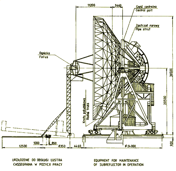
Fig. II.1: Design scheme of the 32-meter radio telescope
maintenance state view
(Z. Bujakowski, Materia³y V Kraj. Symp. Nauk Rad., Toruñ 1987,
part II, p. 66) |
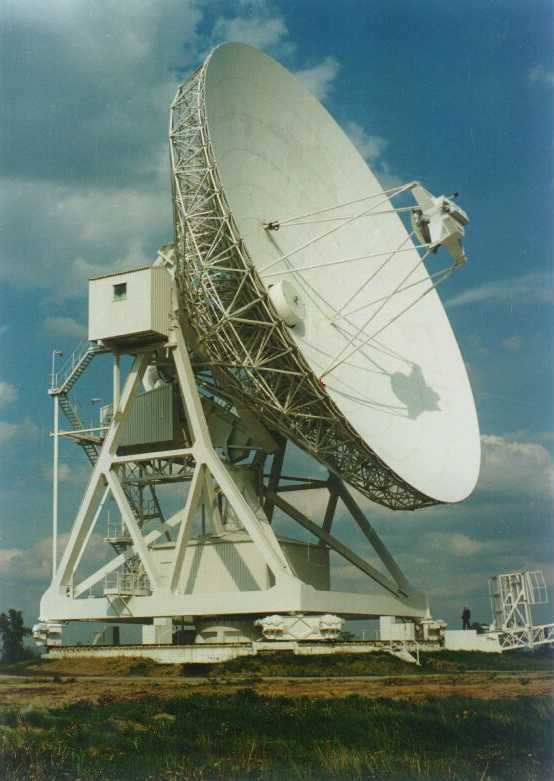
The antenna is a fully steerable telescope with horizontally mounted main
parabolic reflector, 32 m in diameter, and working in classical Cassegrain
mode, the 3.2 m in diameter secondary mirror being a removable hyperboloid
of revolution. The main reflector is made up of 336 panels arranged in seven
concentric rings. Accordingly, there are seven different panels, all of them
having the same length (2.24 m) but width (1.2 ÷ 1.6 m) and shape
varying according to the ring they belong. The reflecting surface
is made of aluminium sheet, 2.5 mm thick, riveted to an aluminium frame
made of T-shaped rails. The sheets have been shaped into a section of the
paraboloid of revolution coarsely by mechanical stretching on special hooves
and finally adjusted with the help of 39 screws mounted so as to be able
to finely deform the underlying frame. The measured mean square deviation
of the panel surface from the pefect paraboloid is smaller than 0.35 mm.
The panels are fixed to the telescope structure with four adjustable screws
at their corners. Measurements made with a laser rangefinder after final
adjustments of the panels have shown that they are set relative to each other
with an accuracy of 0.2 mm.
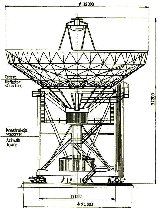 |
Fig. II.2: Design scheme of the 32-meter radio telescope
rest state view
(Z. Bujakowski, Materia³y V Kraj. Symp. Nauk Rad., Toruñ 1987,
part II, p. 66) | |
The telescope can move around two perpendicular axes: fixed vertical and
movable horizontal. The position and speed of the antenna relative to these
axes is measured with absolute precision of 0.001° with the help of 19-bit
angle converters mounted directly on the axes. In order that telescope
movements are smooth and continuous all drives are doubled and
work in the so called antibacklash mode (when one motor pulls, the other
brakes with 10 % of the nominal force of 27.5 Nm).
Gravity distorts the surface figure of the telescope and changes position
and orientation of the secondary mirror which, especially at higher
observing frequencies, may become unacceptable. Temperature variations and
wind can also add to deformation of the figure of the dish. There are two
principal ways to compensate for these distortions. One is special design
of the dish support structure (so called homogenous structure) and the other
makes use of the possibility to move the secondary mirror (which has four
degrees of freedom). Altogether, the steering system consists of 8 motors
in azimuth axis, 4 in elevation axis and 4 for driving the Cassegrain
mirror. Naturally, it incorporates also a computer (HP435rt), number of
electronic drivers, controllers and switches.
The entire construction of the telescope rests on four two-wheelers
(wheels are 1.25 m in diameter) that move along a circular
rail of 24 m in diameter.
|
|
Technical data of the 32 m radio telescope
| Type | steerable parabolic antenna |
|
|
| Optics up to about 1 GHz | prime focus |
|
| above about 1 GHz | Cassegrain system |
|
| Rail track diameter | 24.0 | m |
| Maximum height (above foundation) | 37.6 | m |
| Panels: number (7 rings) |
64+64+64+64+32+32+16 = 336 |
|
| cm |
| Accuracy of manufacturing of the panels (rms) | < 0.35 | mm |
| of panels setting with the help of a templete (rms) | 1.0 | mm |
| of surface adjustment with a laser ranger and theodolite
(rms) | 0.2 | mm |
| of fabrication of the subreflector (rms) | 0.05 | mm |
| of alignment of the subreflector axis with the paraboloid (max) | 0.1 | mm |
| of track leveling (max) | 0.3 | mm |
| of elevation axis leveling (max) | 0.3 | mm |
| Gravitational deformation (dish edge; max) |
4.2 | mm |
| Homology imperfections at the zenith (rms) |
0.11 | mm |
| horizon (rms) | 0.14 | mm |
| Elevation sky coverage | +2 ÷ +95 | ° |
| Azimuth range (origin at South) | ±270 | ° |
| Range of motion of the subreflector along the axis | ±60 | mm |
| of rotation of the subreflector around two axes | ±5 | ° |
| Velocity in the elevation axis |
0.004 ÷ 14.7 | °/min |
| azimuth axis |
0.008 ÷ 31 | °/min |
| Accuracy of tracking (both axes) | 0.002 | ° |
| Aperture blockage by the subreflector and its supports | 7.44 | % |
| Total weight on the rail track | ~620 | t |
| Weight on the elevation axis bearings (including counterbalancing: ~90 t) |
~320 |
t |
| of electrical devices | ~2 | t |
| of central cabin apparatus (under the antenna) | 9.4 | t |
| of steel rails (180 mm in width) | 42.5 | t |
| of the structure for maintenance of the subreflector | ~16 | t |
| Operating wind velocity | 16 | m/s |
| Survival wind velocity | 56 | m/s |
| Maximum ice coverage | 2 | cm |
| temperature range | –25 ÷ +35 | °C |
|
|
In practice, all observational work is carried out with the Cassegrain
system, which uses a hyperbolic secondary mirror
placed between the prime focus and paraboloid vertex. Cosmic radiation
reflected from the paraboloid and then from the secondary mirror is
collected in the secondary focus, which is one of the two foci of the
hyperbolic mirror. Here, near the secondary focus, proper antennas
(feeds) and receivers are placed. Since observations are made in many
widely spaced frequency bands, many receivers and feeds are necessarily
being mounted in the secondary focal plane and the choice of required
receiving system is made by slight tilt of the Cassegrain (secondary)
mirror towards the chosen feed. There exists a possibility to work
in the prime focus mode, useful essentially only for observing at
lower frequencies, say at λ ≥ 50 cm. This possibility requires a removal of the Cassegrain mirror with
the help of special maintenance device, which allows also for
installation of receiving systems in the prime focus cabin.
One of the most important parameters of a telescope is a reflecting
surface accuracy, since it sets limits to highest frequencies at
which a telescope can be used. It is well known that if the surface
has an rms (root mean square) error of σ,
the telescope efficiency is diminished by a factor of
Commonly one assumes that a telescope can be used up to the wavelength
λ = 16σ, at which
the efficiency drops by 54 %
(factor of ησ = 0.54) relative to
the case of a perfect surface*.
The main reflector of
the 32 m telescope is estimated to be accurate to 0.4 mm, which means
that it should have good efficiency at wavelength of 7 mm and possibly
be still usable at 3 mm (about 100 GHz).
*Sometimes
4πσ is taken for the minimum wavelength, at
which the aperture efficiency equals to 1/e, i.e. about 37 %.
II.2 Geometry and Other Characteristics
Optical geometry of a Cassegrain telescope can be fully described
by specifying four parameters. These may be: the main dish diameter (d),
focal length (f), secondary mirror diameter (ds) and placement
of the secondary focus, e.g. its distance from the dish vertex (h). Other
parametrs of interest can then be conveniently calculated from mathematical
formulae given in the following table.
|
|
Geometry of the 32 m radio telescope
| Main reflector (paraboloid of revolution) |
|
| Diameter d | 32.0 | m |
| Focal length f | 11.2 | m |
| f/d ratio | 0.35 |
| Depth of the dish H = d2/(16f) |
5.7143 | m |
| Subtended angle 2Θo
= 4arctg[d/(4f)] | 142.1507 | ° |
| Total surface area
8πf2[cos–3(Θo/2)–1]/3 |
899.45 | m2 |
| Aperture (collecting area) πd2/4 |
804.25 | m2 |
Equation of the parabola
r = √{4f(f–z)} = 2f tg(Θ/2)
|
|
|
Cassegrain mode |
|
| Diameter of the hyperbolic subreflector ds |
3.2 | m |
| Height of the secondary focus above the dish vertex h |
1.0 | m |
| Angle subtended by the subreflector
2Φo
= 2arcctg{2[(f–h)/ds
– (f–H)/d]}
| 18.8256 | ° |
| Effective focal length F =
d/[4tg(Φo/2)] |
97.1729 | m |
| Radio telescope magnification F/f |
8.6762 | |
| Foci separation 2c = f–h |
10.2 | m |
| Eccentricity of the hyperbola c/a = (F+f)/(F–f) |
1.2605 | |
| Inclination of the asymptote
α
= arccos(a/c) = arccos[(F–f)/(F+f)] |
37.5044 | ° |
| Distance of the hyperboloid vertex from its foci c+a |
9.1459 | m |
|
c–a |
1.0541 | m |
| Prime focus subreflector edge distance
ρ =
ds/(2sinΘo) |
1.6914 | m |
| Subreflector depth c–a–(f–H)ds/d |
0.5056 | m |
| Ray path difference to the foci
(f–h)a/c |
8.0917 | m |
| Total
subreflector surface area |
|
πsinα[(ρ+a)√{ρ(ρ+2a)}–2a2ln
| √ρ + √{ρ+2a}
√{c+a}+√{c–a} | ]–π(c2–a2)
|
|
8.7728 | m2 |
| Aperture blockage by the subreflector
πds2/4 |
8.0425 | m2 |
|
Equation of the hyperbola
r = √{(c2–a2)[(c/a–z/a)2–1]}
= (c2–a2)sinΘ
/(a+c cosΘ) |
|
|
r is the distance from the symmetry axis of the
radio telescope, along which the z coordinate is measured. The z
variable origin is at the paraboloid and hyperboloid focus and it is measured
towards the dish. Θ is the angle between
the z axis and the radius vector.
|
Unlike in optical astronomy, in radio astronomy the optical geometry does
not satisfactorily represent telescope properties of prime import to
the user. This is so because of their strong dependence on wavelength
or frequency of observations. Such is e.g. the half power beamwidth
(or angular resolution) of a radio telescope. This parameter and a few
others can be derived from a voltage or power pattern of an antenna.
The voltage pattern is determined by the two-dimensional Fourier transform
of electric field distribution over the aperture. If the aperture has
circular symmetry this transform reduces to the Hankel transform. In particular,
for the aperture in the form of an annulus the normalized voltage pattern
can be expressed by the following approximate (an exact solution is derived
here)
formula:
|
U(x) = |
2d2
(d2 –
ds2)x |
| { |
J1(x) + |
β
2 – β
|
J3(x)
– |
ds
d
|
| [ |
J1( |
xds
d
| )
+ |
β
2 – β
|
J3( |
xds
d
|
) | ] | } |
, |
| (II.1) |
where:
Jn are the Bessel functions of the first kind,
x = π(d/λ)sinθ,
λ = c/ν is the wavelength of observed radiation with the frequency
ν (here c stands for the velocity of light),
θ is the angle between a direction on the sky
and the direction of the telescope symmetry axis,
β represents a taper of the illumination function,
which in this case has been assumed to have the form:
1 – β(2r/d)2,
where r is the distance of a point on the aperture to the symmetry axis.
In this formula for U(x), the components
containing J1 correspond to a uniform field distribution, and those
containing J3(x) to a distribution weighted by
1 – β(2r/d)2.
The antenna power pattern can be written as:
|
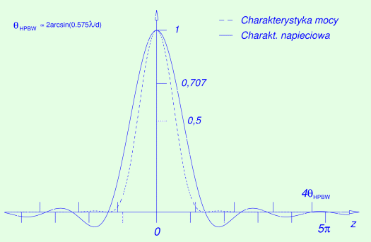
Rys. II.3: Directional pattern for aperture in the form of a ring
or annulus
with the inner diameter 10 times smaller than the outer one (equal to d), the
illumination function diminishing outwardly as 1
3(r/d)2. The voltage pattern (continuous curve) is of the form
of equation (II.1) with β
= 0.75. The broken curve represents the radiation power pattern; it is
the square of the voltage pattern. ΘHPBW
denotes the width of the main power pattern lobe at its half maximum
|
The angular resolution, or half power beam width (HPBW), is equal
to twice the angle θ =
arcsin[xλ/(πd)], at
which the power P falls to 50% of
its maximum value. For a paraboloid with the diameter d = 32 m
numerical calculations give:
|
ΘHPBW = 2arcsin(1.80706 |
λ
πd
|
) ≈ 1.15[rad] |
λ
d |
= 1.24' |
λ
[cm] |
= 37' |
[GHz]
ν |
. |
|
The coefficient of 3.614/π = 1.15 is valid for
d/ds = 10 and corresponds to the illumination function
1 – 3(r/d)2,
i.e. with β = 0.75 which means
10lg(1/β) = 12 dB taper at the dish outer edge.
The following table gives angular resolutions of the 32 m telescope at
some frequencies commonly used in radio astronomical practice.
Theoretical angular resolution
[ΘHPBW =
2arcsin(0.5752λ/d)] for a paraboloidal
dish d = 32 m in diameter with a secondary mirror d/10 in diameter.
Given is also the directivity D (in the last row).
|
| ν
[MHz] | 327 | 408 | 610 |
1420 | 1660 | 2290 | 5000 | 11700 |
22000 | 30000 | 100000 |
| λ [cm] |
91.7 | 73.5 | 49.1 |
21.1 | 18.1 | 13.1 | 5.996 | 2.562 |
1.363 | 0.999 | 0.300 |
|
| ΘHPBW
['] |
113 | 90.8 | 60.7 | 26.1 | 22.3 |
16.2 | 7.41 | 3.17 | 1.68 |
1.24 | 0.371 |
| [°] | 1.89 | 1.51 | 1.01 | 0.435 | 0.372 | 0.270 | 0.124 | 0.053 | 0.028 | 0.021 | 0.006 |
|
| D/1000 | 11 | 17 | 37 | 202 | 276 | 526 | 2510 | 13700 | 48500 | 90200 | 1000000 |
|
|
|
|
|
Define the beam solid angle of a circularly symmetric antenna by:
|
ΩA= |
∫
4π
|
Pn(θ,φ) dΩ ≈ 2
π |
π/2
∫
0
|
|
P(θ)
Pmax
|
sinθ dθ, |
|
where Pn is the normalized power
pattern and Pmax is the power
at the pattern maximum. Then the directivity
D can be calculated from:
D can be interpreted as an approximate
number of discrete sources uniformly distributed over the entire sky given
antenna is able to resolve (in practice so interpreted number is roughly an
order of magnitude smaller).
The fact that the aperture is finite, i.e. that the radio telescope power
pattern is not quite close to the Dirac delta function, means extra losses
in its efficiency. The effective aperture
Aeff is directly related to
the directivity
In the case of the 32 m telescope one finds:
This quantity naturally does not account for the ohmic losses and assumes
a perfect shape of the reflecting surface as well as the absence of any shadowing
effects. Therefore, in practice the effective area or aperture is determined
by observations of radio sources of known flux density, F. If such a source
rises the system temperature (see Chapter VII
for definitions of various temeperatures) by TA then
where k is the Boltzmann constant.
II.3 Shadows of the Secondary Mirror and Its Support Struts
At longer waves the effect of blockage of incoming radiation by support
structures of the secondary reflector (or feeds mounted at the prime
focus) limits usefulness of a telescope. The effect becomes more
pronounced as the wavelength increases. One may assume total
overshadowing of the feeds by the support legs, when a mean separation
between the legs reaches about half of the wavelength. This criterion applied
to the Toruñ design would allow for observations even below 100 MHz. It
is assumed however, that the 32 m telescope will never be used below the
lowest standard VLBI frequency 327 MHz.
Still the aperture blockage remains an important factor because it affects the aperture efficiency. It is estimated that the efficiency
decreases by the following factor
|
ηb
= | ( |
1 – |
blocked area
total aperture area |
) |
2
|
. |
|
Three components contribute to the blocked area: (1) direct shadow cast by
the subreflector, (2) similar shadow of the supporting struts, and (3) shadow
of the struts due to blockage of the spherical wave reflected from the dish and
converging towards the focal point. The first two components are relatively
easily calculable. The third component may pose a difficulty, especially in
designs in which the struts do not lie in the plane passing through the dish
axis, which is the case with the 32 m telescope that has 8 legs to support
the Cassegrain mirror. Both, an original
analytical
solution to the mentioned problem of skewed struts and a graphical
projection lead to about
7.44 % for the loss of aperture area, which converts into about 14 %
loss in antenna efficiency due to aperture blockage alone.
|
Components of the shadow per 1/8 of the aperture |
| Shadow source | Size
[m] | Area
[m2] |
| Subreflector | π×1.62/8 | 1.0053 |
| Arm inner part |
~0.150×1.10 |
0.1650 |
| Arm outer part |
0.100×0.42 |
0.0420 |
| Strut thinner part (parallel projection) | 0.114×1.97 | 0.2246 |
| Strut thicker part (parallel projection) | 0.159×2.28 | 0.3625 |
| Strut type (3) blockage | anal. solution | 5.6407 |
| Total shadow area |
| 7.4821 |
|
| In percent of the aperture 100×8×7.4821/804.25 = 7.44 |
|
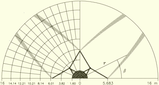
Rys. II.4:
Mesh
of panels and blocking
shadows as projected on the aperture plane of the Torun 32-meter radio
telescope. This drawing is to scale. Area shaded lightly (outer shadow)
is equal to 22.56 m2, and the black one 7.62 m2.
All curves limiting the outer shadow of a single strut are arcs of a circle.
The two longer sides can be expressed as a function of the radial distance
r thus: β(r) =
βo –
arccos[r/(2ro) –
2f2/(rro)], where f is the focal length (11.2 m),
and βo and ro
equal to 2.3345 rad and 60.987 m for one shadow side and 2.2789 rad
and 62.043 m for the other |
II.4 Blind spot near the zenith
All horizontally (alt-az) mounted telescopes are unable to track celestial
objects in a small region on the sky near the zenith wherein the diurnal
rotation of the sky transformed into azimuthal speed exceeds the maximum
speed of a telescope azimuth drive. It can be easily understood by
noting that the azimuth of an object passing exactly through the zenith
changes in infinitely small time by 180°, i.e. from 270° (or 90°) to 90°.
So also, the closer an object passes by the zenith, the faster are changes
of the azimuth. It
can
be shown that when the maximum speed of such telescope equals 30°/min
a spot in the vicinity of the zenith where the azimuthal speed exceeds this
value has approximate dimensions of 0.5°×1.5°.
|
Rys. II.5: Left. Circumzenithal region where the
mean azimuthal velocity of cosmic objects is greater then 31°/min at
the geographical latitude φ = 53.1°. The axes
of this diagram are the declination (in degrees) and hour angle (in minutes of
time). Right. The time ('Czas przej.' in minutes) required by
the telescope to catch up with the object on the other side of the local
meridian. The apparent symmetries with respect to declination equal to
φ are only due to the smallness of the differences |
The velocity in the azimuth A for a celestial object due to its diurnal
rotation is equal to
|
|
.
A
|
= |
sinφ –
sinδ cos z
sin2z
|
= sinφ + cosφ |
cosA
tg z
|
, |
|
where φ is the geographical (geodetic) latitude,
δ the declination of the object, and z its
zenith distance (i.e. π/2 minus the elevation or
altitude angle). The critical region, wherein a telescope with the maximum
tracking speed in the azimuth of V, expressed in natural units of rad/rad
or (telescope rotations)/(sky rotations) and defined to be negative for
objects transiting between the zenith and the celestial pole (i.e. on the
Northern hemisphere for δ > φ),
lags behind tracked objects lies between these two declinations:
|
δ± = φ –
arctg |
cosφ
±V – sinφ
|
, |
|
thus constitutes a belt δ– – δ+
= ~(2/V)cosφ in width.
In particular, for the location of Piwnice (32 m telescope) and V = 120
(i.e. 30°/min) one obtains δ– –
δ+ = 34.4'.
The hour angle at which a tracked object will start to escape the telescope can
be calculated exactly (see e.g. Eq. (9) in
this
paper) but for practical purposes such a solution is too involved. Instead,
this simple expression can be used as a very good approximation:
The quantity Ao ≈ –arccos√{(φ – δ)
(±V – sinφ)/cosφ}
is the corresponding hour angle. Both these angles are assigned negative
sign because at this time the object is East of the meridian.
File first posted on 23 Feb 2004.
