 | SCIENTIFIC INSTRUMENTATION |
| Nauch. apparat., 1987, 2, 2, 69–75 | PL ISSN 0257-3881 |
FEED SUPPORT BLOCKAGE AREA
IN PARABOLIC ANTENNAS
K. M. BORKOWSKI, A. J. MACIEJEWSKI*
Toruń Radio Astronomy Observatory,
Nicolaus Copernicus University
ul. Chopina 12/18, 87-100 Toruń, Poland
* Institute of Astronomy, Nicolaus Copernicus University,
ul. Chopina 12/18, 87-100 Toruń, Poland
| Exact analytical solutions for calculating the shape and area of shadows cast by feed support legs which are oriented arbitrarily with respect to the main axis of parabolic antennas are presented. An example is given for a 32 m radiotelescope planned for the Toruń Radio Astronomy Observatory. A FORTRAN subroutine for computing the shadow effective area is included. |
One of the factors contributing to the gain reduction of parabolic
antennas is the blockage of the incoming radiation by a subreflector or
feed mount and its support struts. The amount of losses depends in the
first place on actual structural design of a radio telescope, aperture
illumination function and operating frequency. To the best of our knowledge
there is no theory which would allow an exact account for these losses [1].
The usual practice is to find the shadow area, weighted by the aperture
illumination, by graphical projection. This procedure is questionable
when the dimensions of the blocking obstacles are of the order of a wavelength,
because the radio shadow is then much wider than the optical
shadow. For many reasons, however, the optical projection is very useful,
first approximation to the real situation.
Most of the feed support structures in contemporary radio telescopes have the form of equiangular tri- or quadrupods whose vertices lie somewhere above the prime focus of a telescope. Ruze [2] has derived relatively simple formulae approximating the shadow area and gain loss for such strut configurations. More recently supports with struts skewed with respect to the main axis of the paraboloid have begun to appear. The 15 m millimeter UK/Netherlands telescope on Mauna Kea and one of the designs of a 32 m telescope planned for the Toruń Radio Astronomy Observatory are examples. In these cases the axis and strut no longer lie in the same plane. Quite naturally, literature is silent about practical procedures to calculate the shadow cast by such constructions. We set out to derive exact formulae for the shadow area, which cou1d be considered as both an improvement on, and generalization of Ruze's findings.
The optical shadow projected on the aperture plane consists of three parts [2]. Since the inner two parts can be dealt with straightforwardly by using conventional precedures, we shall limit ourselves to considering only the outer portion — the shadow of the struts caused by the spherical wave converging towards the feed or effective focal point. On the aperture plane the shadow is seen as composed of fan-shaped regions. Their area is determined by the orientation of the struts relative to the paraboloid axis, their lateral dimensions and the telescope parameters: radius rmax, and focal length f.
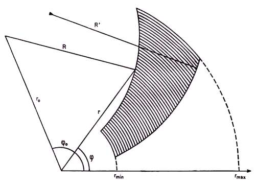
The analysis that follows refers to one fan-shaped region of the shadow (Fig. 1), corresponding to one of the legs of the support structure. Before going into details the reader will observe that the elongated shadow sides are determined by the section of two planes and the paraboloid of revolution. The planes pass through the prime focus of the paraboloid and are tangent to the strut on either side. Given the geometry and orientation of the strut it is a matter of elementary analysis to find directional cosines of both the planes. Let n denote versor normal to one of the plains so chosen that n3 is positive. Then on the aperture plane, (x, y) whose origin is at the focus, the equation of the shadow side corresponding to that plane will be
 |
| Fig. 1. Schematic drawing of aperture plane projection of a shadow cast by a skewed strut fixed to the parabolic dish surface at rmin. The shadow area is bounded by 4 circular arcs whose radii are rmin, rmax, R = 2f/n3 and R' = 2f/n'3 |
| (x + 2fn1/n3)2 + (y + 2fn2/n3)2 = (2f/n3)2. | (1) |
This can be recognized as the equation of a circle. In the polar coordinates (r,φ) with the same origin the circle is conveniently described by either
| φ(r) = φo – sign(φ o) arccos[(r2 – 4f2)/(2 r ro)] | (2) |
or its inverse
| (3) |
|
| (4) |
where f(r) stands for the illumination function and rmin is the radial distance of a point, at which the strut intersects the dish surface. Though, unfortunately, the function (2) is not directly integrable (since it leads to the elliptical integral) the integral (4) can be usefully evaluated numerically, given the f(r). Nevertheless, S can be obtained analytically using function (3) and for some simple forms of f(r). For brevity we shall omit here the details of somewhat tedious derivation and present only the results of such an approach. Let
| U(α,g) = {g P(α,g) + sin[P(α,g)]} 4f2/(g – 1/g), | (5) |
| P(α,g) = α + arcsin[sin(α)/g] | (6) |
then the projected area of shadow region (with f(r) = 1) is given by
|
| + U(φ1 – φo′,g) + U(φ2′ – φo′,g′) – U(φ1′ – φo′,g′)], | (7) |
where φ2 = φ(rmax), φ1 = φ(rmin) and the primed quantities refer to using φ′(r) instead of φ(r). If an illumination taper is assumed to be of the form f(r) = 1 – a(r/rmax)2, the effective area can be found from
|
| – D(φ2 – φo,g) + D(φ1 – φo,g) + D(φ2′ – φo′,g′) – D(φ1′ – φo′,g′)], | (8) |
|
D(α,g)
= {(g2 + 2)P(α,g)
+ [3g + 1/g + cos(P(α,g))]× ×sin(P(α,g))}(2f)4/(g – 1/g)2. | (9) |
Formulae (5) through (9) represent the exact analytical solution to the problem of finding the shadow area of skewed feed support legs, as projected on the aperture plane. Although there should be no difficulty to program the presented algorithm, for the convenience of the reader, we enclose an Appendix with a listing of a FORTRAN subroutine SHADOW along with an example of a simple calling program. We have checked the subroutine against numerical integration carried out according to (4). Here follows an example from our study of the mentioned Toruń design.
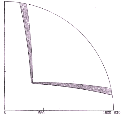
The 32 m telescope (rmax = 16 m) is assumed to have the focal length f = 11.2 m and feed support composed of 8 cylindrical legs, each 0.159 m in diameter, and each attached so that it casts a shadow of the same shape and area. Two of (x, y, z) points, through which the axis of one of the struts passes are (5.719, 0.0, –10.5764) and (2.1213, 2.1213, 0.38) (in meters).
 |
| Fig. 2. The outer part of the feed support blockage area of the Toruń 32 m radio telescope. The figure is to scale. The dashed region is here 11.28 m2 |
This gives 5.6869 m for rmin. The resulting shadow shape is shown in Fig. 2 and its area calculated in accordance with (7) is 5.64 m2, which is 6.42% of one eighth of the aperture area outside rmin. With a typical 12dB illumination taper (a = 0.75) the effective area falls to 3.2 m2, which translates to 6.31% of the effective area outside rmin (8×50.73 m2).
ACKNOWLEDGEMENTS
K. M. Borkowski would like to gratefully acknowledge a financial support from Polish Academy of Sciences through research problem Nr. l02a.
REFERENCES
| 1. | RUSCH W. V. T., Analysis of Paraboloidal — Reflector Systems, Methods of Experimental Physics, 12B, 29 (1976). |
| 2. | RUZE J., Feed Support Blockage Loss in Parabolic Antennas, Microwave J.,11, 12, 76 (1968). |
 |
c
c     Sample calling program for subroutine SHADOW
c
      dimension xyz1(3), xyz2(3)
      data xyz1,xyz2/5.719,0.,-10.5764,2.1213,2.1213,.38/
      data f,rleg,taper,rmax/11.2,.0795,.75,16./
      call SHADOW(xyz1,xyz2,rmax,f,rleg,taper,areaeff)
      write(6,11111) areaeff
11111 format(//1x,'Effective area = ', f10.6)
end |
      subroutine SHADOW(xyz1,xyz2,rmax,f,rleg,taper,areaef)
c
c     This subroutine calculates an effective area of the shadow
c     cast by a feed support leg arbitrarily oriented with respect
c     to the main axis of a parabolic reflector.
c
c     Description of parameters:
c
c         xyz1, xyz2 - one dimensional arrays containing the three
c                      cartesian coordinates of two points lying on
c                      the leg axis.
c
c               rmax - the reflector radius.
c
c                  f - the focal length of the paraboloid.
c
c               rleg - the radius of the leg
c
c              taper - the illumination taper parameter. Illumination
c                      function is assumed to have the form:
c                             1 + taper*(r/rmax)**2
c                      where r is the distance from the paraboloid axis.
c
c             areaef - the effective area of the shadow as projected on
c                      the aperture plain.
c
c     Remarks
c
c     The units for xyz1, xyz2, rmax, f and rleg are arbitrary but the
c     same. Areaef is output in these units squared.
c     It is assumed that  xyz1(3) .lt. xyz2(3) .
c
c

      double precision xn(3),xn1(3),xn2(3),r1(3),r2(3),a,b,c,D,del,
     *dr1,dr2,dx1,dx2,dx1x2,dr1r2,ff,f0,f1,f2,f0p,f1p,f2p,g,gp,
     *P,pom1,pom2,r0,r0p,tt,tak,U,fi
      dimension xyz1(3),xyz2(3)
c
c     Statement functions
c
      P(a,g)=a+dasin(dsin(a)/g)
      U(fi,g)=(g*P(fi,g)+dsin(P(fi,g)))*ff*ff/(g-1/g)
      D(fi,g)=((g*g+2)*P(fi,g)+(3*g+1/g+dcos(P(fi,g)))*dsin(P(fi,g)))*
     1         (ff*ff/(g-1/g))**2
c
c     Find the lower limit of the shadow
c
      dr1=xyz1(1)**2+xyz1(2)**2
      dr2=xyz2(1)**2+xyz2(2)**2
      dr1r2=xyz1(1)*xyz2(1)+xyz1(2)*xyz2(2)
      a=dr1+dr2-2d0*dr1*dr2
      b=2.d0*(dr1r2-dr1)-4.d0*f*(xyz2(3)-xyz1(3))
      c=dr1-4.d0*f*(xyz1(3)+f)
      tt=0.5d0*(-b-dsqrt(b*b-4.d0*a*c))/a
      rmin=dsqrt(4*f*(xyz1(3)+(xyz2(3)-xyz1(3))*tt+f))
c
c     Rotate the focal plane.
c
      ff=f+f
      t=(rmin**2/(2.d0*ff)-f-xyz1(3))/(xyz2(3)-xyz1(3))
      al=atan2(xyz1(2)+(xyz2(2)-xyz1(2))*t,xyz1(1)+(xyz2(1)-xyz1(1))*t)
      c=cos(al)
      s=sin(al)
      r1(1)= c*xyz1(1)+s*xyz1(2)
      r1(2)=-s*xyz1(1)+c*xyz1(2)
      r1(3)=xyz1(3)
      r2(1)= c*xyz2(1)+s*xyz2(2)
      r2(2)=-s*xyz2(1)+c*xyz2(2)
      r2(3)=xyz2(3)
c
c     Determine vector normal to the axis of leg
c
      xn(1)=r1(2)*r2(3)-r2(2)*r1(3)
      xn(2)=r1(3)*r2(1)-r2(3)*r1(1)
      xn(3)=r1(1)*r2(2)-r2(1)*r1(2)
c
c     Determine vector normal to plains tangent to the leg
c
      dx1x2=r1(1)*r2(1)+r1(2)*r2(2)+r1(3)*r2(3)
      dx1=r1(1)*r1(1)+r1(2)*r1(2)+r1(3)*r1(3)
      dx2=r2(1)*r2(1)+r2(2)*r2(2)+r2(3)*r2(3)
      tak=rleg/dsqrt(dx1*dx2-dx1x2**2-rleg*rleg*(dx1-2.d0*dx1x2+dx2))
      do 10 i=1,3
       del=((dx2-dx1x2)*r1(i)+(dx1-dx1x2)*r2(i))*tak
       xn1(i)=xn(i)+del
       xn2(i)=xn(i)-del
   10 continue
c
c     Find polar parameters of the shadow
c
      f0 =datan2(-xn1(2)*xn1(3),-xn1(1)*xn1(3))
      f0p=datan2(-xn2(2)*xn2(3),-xn2(1)*xn2(3))
      pom1=(rmin-ff)*(ff+rmin)/(2.d0*rmin)
      pom2=(rmax-ff)*(ff+rmax)/(2.d0*rmax)
      r0 =ff*dsqrt(xn1(1)**2+xn1(2)**2)/dabs(xn1(3))
      r0p=ff*dsqrt(xn2(1)**2+xn2(2)**2)/dabs(xn2(3))
      f1=f0-dsign(dacos(pom1/r0),f0)
      f2=f0-dsign(dacos(pom2/r0),f0)
      f1p=f0p-dsign(dacos(pom1/r0p),f0p)
      f2p=f0p-dsign(dacos(pom2/r0p),f0p)
      df1=f1-f1p
      df2=f2-f2p
      g =dsqrt((ff/r0)**2+1.d0)
      gp=dsqrt((ff/r0p)**2+1.d0)
c
c     Find the shadow area and its effective area
c
      area=0.5*(rmax**2*df2-rmin**2*df1-U(f2-f0,g)+U(f1-f0,g)
     *          +U(f2p-f0p,gp)-U(f1p-f0p,gp))
      areaef=abs(sngl(area-(0.25*taper/rmax**2)*(rmax**4*df2-rmin**4*df1
     *          -D(f2-f0,g)+D(f1-f0,g)+D(f2p-f0p,gp)-D(f1p-f0p,gp))))
      return
end |
|
Note on this electronic version of the paper A few mistakes or misprints in the published version were corrected. These were generally minor ones but there was a more significant error that made the Eq. (8) therein invalid (omitted term a/r2max); luckily the subroutine SHADOW was not affected. This subroutine was now (in 2002) reconstructed (the original has been lost) for the purpose of including in the present web publication and compiled with the Lahey compiler LF90 (v. 4.5) with no problems whatsoever. Executing the compiled code should result in the following response:Effective area = 3.202006(possible difference in the least significant digit should not be considered alarming). However, calculation of rmin in this routine is only approximate, and although adequate for this example it should not be recommended in general. More recently (in 2012) the SHADOW routine has been tested extensively and in the process improved considerably (exact calculation of rmin inclusive). Its new version, SHADOW2 (see below), may be of interest to wider readership not only because of the mentioned improvement, but also because it returns, besides areas, all parameters necessary for analytical description of shadows. The example in the following printout returns such data (see the commented out end part of the main program) for Torun 32-metre telescope, which has each strut skewed and composed of two cylindrical parts of different diameter. The reader may just mark this FORTRAN listing, copy it to the clipboard and save to a file to have a source code ready for modifications and compilation. Since it is written in a pretty standard language it should be smoothly digested by a variety of compilers. Here (see figure Rys. 4 therein) is a report that used results from this example to compute quite realistic (although also quite complex) radiation patterns of the telescope. Be aware that the algorithm employed in SHADOW and SHADOW2 cannot tackle the trivial case of support legs parallel to the paraboloid axis (because then the shadow circular sides degenerate to straight lines, or circles of inifinite radius). However, this case can be easily dealt with directly as the shadows become just radial sections of circular aperture.
|
File originally translated from
TEX
by
TTH,
version 3.13 on 25 Sep 2002. |
Last modified: 19 July 2012 | |