ACTA ASTRONOMICA
Vol. 37 (1987) pp. 79–88
Near Zenith Tracking Limits
for Altitude-Azimuth Telescopes
by
K. M. Borkowski
Toruñ Radio Astronomy Observatory,
Nicolaus Copernicus University,
ul. Chopina 12/18, PL-87-100 Toruñ, Poland
Received June 10, 1986
|
ABSTRACT The diurnal rotation of the, sky, when
viewed in the horizon system of coordinates, exhibits a singularity at
the zenith where the angular azimuthal speed and acceleration are infinite.
This prevents all telescopes of the altitude-azimuth mounting, no matter
how good is their performance, to be able to track celestial objects in
a small region of the sky about the zenith. A simple algorithm to determine
the shape and size of this blind spot is presented. An example is given
for the projected 32-m radio telescope to be located near Toruñ.
|
1. Introduction
It is known that both radio and optical telescopes with the altitude-azimuth
mounting fail to follow the diurnal rotational motion of the sky
in a close neighbourhood of the zenith. The extent and shape of this blind
circumzenithal spot depends in a complicated way on the maximum velocity
and acceleration which can be attained by the azimuth drive. Since,
in practice, the spot is small in size this inability of tracking is a rather
minor disadvantage of the mounting. Nevertheless, it is clearly important
for the telescope designer, as well as for the user, to be aware of its existence
and nature. Possibly the best insight into nature of this drawback
is gained through noting that the closer a celestial object passes the zenith,
the less time it needs to swing between two arbitrarily chosen vertical
circles, which define the angular range a telescope must rotate.
Some formulae for estimation of the dimensions of the blind spot
have been given by Watson (1978), but his equations are all expressed
in the azimuth-zenith distance coordinate system, what makes them inconvenient
for certain practical applications. In particular, this is the
case with all problems related to analysis of the time behaviour of the
telescope while traversing the spot during tracking an object with a critical
declination. In this paper we present a simple algorithm to compute all
important quantities related to the blind spot and expressed as functions
of the hour angle (or sidereal time) and declination. Most of these equations
were originally developed, prior to familiarizing ourselves with the Watson's
work, for an investigation of the blind spot of the projected 32-m
radio telescope of the Toruñ Radio Astronomy Observatory (Borkowski
1986). Therefore, all illustratory examples concern this telescope and
geographical location of the Observatory. It will be noted, however, that the
examples are pretty typical and easy to rescale.
The next two sections contain the above mentioned algorithm. In
section 4. we present further study which is intended to validate the
assumption underlying the algorithm that other theoretically possible
limitations are unimportant for a typical radio telescope and in particular
can be safely neglected with the Toruñ design. Another set of formulae is
given for the case when the azimuth drive acceleration may be a liiiting
factor.
2. Basic relations and definitions
Most of textbooks on spherical and practical astronomy give formulae
necessary to transform coordinates of the equatorial system, i.e. the
declination δ and hour angle t, to the horizon
system, i.e. the zenith distance z and azimuth A, given the observer's
geographical latitude φ. They can
be conveniently condensed into the following equations:
|
z(t) = arccos(sinφsinδ + cosφcosδcos t), | (1) |
|
A(t) = arctg[sin t/(sinφcos t – cosφtgδ)], | (2) |
|
p(t) = arctg[–sin t/(sinδcos t –
cosδtgφ)], | (3) |
which are in the form of functions of the hour angle. Both the azimuth
and the parallactic angle, p, are defined to lie in the range from
–π to
π
(westward positive) centered at the observer's meridian (south of the zenith),
the quadrant being determined by relative signs of the numerator
and denominator of the arctangent function arguments (Eqs. 2 and 3).
We denote the rate of change, or velocity, by placing a dot above the
corresponding coordinate [to avoid awful setting of
the dotted symbols in html language this web version has the time derivatives
or velocities distinguished by a prime mark
(′)]. By differentiating the three above
functions with respect to t we have for velocities
|
A′ = sinφ
+ cosφcosA/tg z
= |
sinφ –
sinδcos z
sin2z
| ,
|
| (5) |
|
p′ = cosφcos A/sin z, | (6) |
which, by virtue of Eqs. (1) and (2), can be understood as functions of
time. Here, natural units are assumed, i.e. rad/rad, which can be converted
to deg./min. through a multiplicatory factor of 0.25 (more precisely,
this factor should be increased still by about 0.3% to account for the
difference between solar and sidereal time).
The Eq. (4) discloses that the absolute changes of the zenith distance
are never faster than these of the hour angle, while velocities in the azimuth
and parallactic angle may reach arbitrarily high values as z approaches 0.
Since the parallactic angle carries somewhat different meaning and lesser
importance and, in fact, its behavior near to the zenith resembles very
much that of the azimuth, it becomes clear that the most serious impact
on the blind spot arises from azimuth drive limitations, and in particular
from its finite velocity.
3. Blind spot due to azimuth velocity
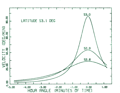
The rate of change of the azimuth (Eq. 5) can be shown (see also Fig; 1)
to possess an absolute maximum at the transit, where its value is
|
A′ =
cosδ/sin(φ – δ)
. | (7) |
The circumpolar objects, as evidenced by this expression, have both
positive and negative azimuthal velocities. The change of sign takes place
at hour angles equal to ±arccos(tgφ/tgδ),
the angles at which
A′ = 0. An altitude-azimuth telescope tracking
the diurnal motion of an object with a fixed declination will keep pace with
it until a point, east of the meridian, where A′
of Eq. (5) reaches the maximum allowable speed of the telescope, V. To keep
our notation simple it is assumed that this limiting value of the azimuth
drive is signed according to the actual direction of object's motion during
the meridian passage: V = |V| sign(φ – δ).
 |
Fig. 1. Azimuth velocity of the sky near the zenith at the geographical
latitude 53.1° for three declinations shown above each maximum (in degrees).
The curves are symmetrical with respect to the meridian and approximately
the same (but for negative velocities) for declinations 53.2°, 53.3° and 53.4°.
|
|
Considerations on the actual sky velocity, and specifically at the meridian
(Eq. 7), immediately lead to the conclusion that limitation to the
tracking refers only to objects whose declination lies in the range
|
φ – arctg |
cosφ
|V| – sin
φ
|
< δ < φ
+ arctg |
cosφ
|V| + sinφ
|
. |
| (8) |
This inequality can serve to determine the north-south extent of the
blind spot. Objects with declination satisfying this condition begin to move
faster than the telescope is able to, at the moment for which the hour
angle is
to = –arccos |
|
sinδ( | 1
2V
|
– sinφ)
+ | √ |
|
1 + ( |
sinδ
2V
|
)2
– |
sinφ
V
|
|
cosδcosφ
|
,
|
|
(9) |
obtained by solving Eq. (1), subject to the condition
A′ = V, for t = to.
Though Eq. (9) is exact, admittedly it is not simple enough for quick and
easy reference. If, however, a small loss in accuracy is admissible this
equation can be much simplified to
which exhibits extrema of about –0.5/|V| at
the azimuths of –π/4
and –3π/4,
corresponding to objects' declination of
While Eq. (9) gives an exact eastern boundary of the blind spot, the
above approximations may be used for rapid estimates, whose accuracy
will probably satisfy even a quite demending steering program designer.
Assuming that while lagging (over the spot) the telescope rotates
with its highest speed in the azimuth and keeps due pace with the tracked
object in the altitude, the increasing angular separation between the object
and the telescope direction can be expressed by
|
θ(t) = 2 arcsin[sin z(t) sin |
A(t) –
Ao – (t – to)V
2
|
], |
| (12) |
where
|
Ao = A(to)
+ π[1 – sign(φ – δ)]. |
(13) |
At this point it is of no real importance that the definition (13) includes
a 2π shift of azimuth. It is meant for a later use where it will effectively
help to avoid problems resulting from a discontinuity inherent in the
conventional definition of this coordinate when the transit of objects with
δ > φ is involved. It poses no difficulty to observe that the separation (12)
is greatest at t = –to, so that
|
θmax =
2arcsin[cosδsin to
sin(Vto –
Ao)/sin Ao]. | (14) |
From this moment the telescope regains the lost distance and eventually
catches up with the object at some hour angle greater than –to
(west of the meridian). For the time of reacquisition, at the western boundary
of the blind spot, the following transcendental equation obviously holds
|
t+ = to + [A(t+) –
Ao]/V. | (15) |
It is of moment to note that V given above is slew velocity and may
sometimes be greater than the maximum tracking velocity. The solution that
follows is clearly affected by distinguishing between V and, say,
Vslew in Eq. (15).
In solving for the hour angle of the western edge of the blind spot,
t+, we adopted the Newton's method. The following guess for
start proves very efficient:
It allows the first iteration step,
|
t+ = t1 – |
A(t1) –
Ao – (t1
– to)V
A′(t1) – V
|
|
| (17) |
to yield results that are overestimated by less than 1 second of time (as
deduced from numerical computations). Since a real telescope misses objects
during traversing the spot for somewhat longer time than that implied
by t+ – to of Eq. (15)
(allowence must be made for the finite deceleration
with which the telescope slows down its highest speed to match the actual
sky rotation at the reapproach), we find ourselves on the safe side
accepting the solution (17).
 |
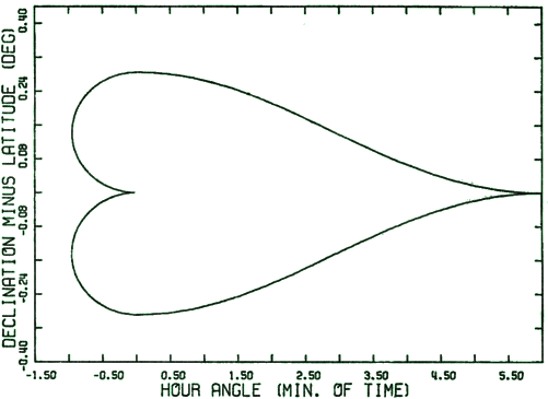
Fig. 2. Example of a near zenith region in which a telescope at the
geographical latitude of 53.1° and with maximum angular speed in the azimuth
of 120 times that of the sky, i.e. 30°/min., lags behind would be tracked
astronomical objects. The apparent symmetry about the δ – φ = 0
axis is an illusion caused by smallness
of the differences. |
|
Formula (17) completes our determination of the zenithal blind spot
in the hour angle-declination coordinate system. The presented algorithm
gives the optimal solution, i.e. the smallest spot. In fact, the spot has
a peculiar shape, as depicted in Fig. 2. It will be noted, however, that
the shape varies significantly with the choice of other schemes of driving
the telescope through it. Worthy mentioning is, for instance, the procedure
of symmetrizing the blind spot as described by Watson (1978), which results
in entirely different shape. We observe that our algorithm would produce
the western boundary of such a spot if we had chosen deliberately to = 0
in Eqs. (13) and (15). We have found that, as could be expected, the symmetric
spot is slightly wider in the east-west direction than the optimal one.
At the far-from-zenith end the widening is the largest (but less than 20%
for examined La Palma and Toruñ telescope cases) and vanishes as declination
nears that of the zenith. The extra time needed for pass over the
symmetric spot is necessarily unimportant since it will usually be well
below 1 minute of tracking time. It should be born in mind, however, that
the procedure requires the telescope control programs to incorporate in
one or another way the a priori limits, which are not directly
related to the actual motions of the telescope and tracked object.
To get a practical example of the use of our algorithm consider a telescope
with maximum speed in the azimuthal axis overriding the diurnal
sky rotation by a factor of 120 (|V| = 120, or 30°/min.), and located at
the geographical latitude φ = 53.1°. Such
a telescope cannot track astronomical objects with declination between
52.8° and 53.4° (Eq. 8), beginning with hour angles (to, Eq. 9)
of –0h0.96m corresponding to the declination of
52.95° (Eqs. (10) and (11) give –0h0.95m and
52.96°, respectively). The east-west extent of the spot (t+
– to calculated from Eqs. 15 to 17)
has a maximum at δ = φ
of about 6 min. (this value can also be rapidly approximated by t1
from Eq. (16), where Ao = –π/2
and to = 0). The complete limits
for tracking of this example are presented in Fig. 2, which
has been computed using Eqs. (9), (13), (16) and (17) with (2) and (5)
as user defined functions in FORTRAN programming language. In the
scale of this figure an approximate solution based on Eq. (10) is
indistinguishable from this actually displayed.
In radio astronomy the radio telescope directivities allow to see sources
which are sometimes considerably away from the direction of maximum
gain. This narrows the region of ineffective tracking, assuming some loss
of antenna gain can be tolerated. In this case, the limits for effective
tracking can be found by using the actual angular mispointing as expressed
by Eq. (12). Given the tolerable θ(t) <
θmax (Eq. 14), Eq. (12) can be
solved for t = toNew and t = t+New to yield the new
limits (provided there are any, i.e. the solutions satisfy the inequality
to < toNew < t+New < t+).
4. Other limitations
There are number of other theoretically possible limiting factors to
the tracking near the zenith. These concern the finite azimuth drive
acceleration, and the velocity and acceleration of the altitude and field
rotation drives. This section is devoted to their brief discussion to conclude
that in practice the blind spot is determined by the azimuth drive alone.
The sky acceleration in the azimuth is
|
A′′
= –cos2φsin(2A)
(1 + ctg z tgφ/cos A
+ 2 ctg2z)/2. | (18) |
This equation is quadratic in ctg z and, after solving with the use of
the normal quadratic formula, can be used to construct an equal
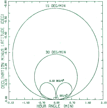
acceleration contour (Fig. 3). In a close vicinity of the zenith the contour
can be conveniently approximated by
 |
Fig. 3. Southern part of the equal azimuthal velocity (positive) and
acceleration contours at the geographical latitude of 53.1°. The eastern lobes
(to the left) refer to the positive accelerations and western ones to the
negative. The northern part is approximately symmetrical about the hour angle
axis except that the signs of velocities and accelerations are reversed.
|
|
|
tg z = cosφ[ |
sin(2A)
–a | ]1/2 |
| (19) |
or, in terms of the hour angle,
|
tg t = sin A [ | sin(2A)
–a |
]1/2, |
| (20) |
where A′′ is set to a, the maximum azimuth
drive acceleration. The contour due to acceleration (20) intersects that for
the velocity (10) at (for illustration see Fig. 3)
|
δ*
= φ ± |
4V3
a2 + 4V4
|
cosφ, |
| (21) |
|
t* = –arctg |
2aV
a2 + 4V4
|
. |
| (22) |
Eqs. (21) and (22) are interpreted to determine approximately the region
around the zenith where the blind spot due to acceleration limit is larger
in the east-west direction than the velocity spot. Analysed examples entitle
us to add again that, although the Eqs. (19) to (22) are all approximations,
they are nevertheless very accurate near the zenith due to
the smallness of the zenith distances and hour angles involved.
 |
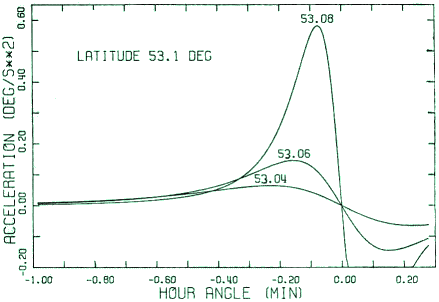
Fig. 4. Azimuth acceleration near the zenith at the latitude of 51.1° plotted
for three declinations (as indicated by the numbers shown above corresponding
maxima, in degrees). The cur.ves are odd functions of the hour angle. The
graphs for declinations symmetrical with respect to 51.1° (north of zenith)
look essentially the same, except that the accelerations are oppositely signed.
|
|
On passing to a conerete example note that in practice radio astronomy
telescopes have accelerations in both axes of the order of, but frequently
exeeeding, 1°/s2 which corresponds to about 3.3·106 of natural
units (rad/rad2). Assuming this value for the limit of attainable
acceleration and our earlier V = 120 gives –1s
for t* (Eq. 22) and a belt
0.26"cosφ in width in declination centered at the zenith (Eq .21). This
is evidently negligibly small region. Restricting the tracking acceleration to
0.02°/s2 enlarges the region of dominant acceleration limit to
–0.7m and 9.2'cosφ,
respectively. The eastern edge of the combined spot is in general the outer
envelope of the two contours and its shape can easily be inferred from
Fig. 3, where two contours of each type are plotted superimposed in the
same coordinate system. It is clear now that in most practical cases the
acceleration contour lies almost entirely inside the velocity contour. Be it
desirable, however, the simplest way to incorporate the acceleration limit
into our algorithm is to set to of Eq. (9) at t* for declinations enveloped
by the two of Eqs. (21). Noteworthy, this problem disappears altogether
if earlier mentioned procedure of symmetrizing the blind spot is adopted
in a steering telescope control program.
As already noted, Eq. (4) shows that velocity in the zenith distance
(or altitude) is less than or equal to 1 rad/rad, or l°/4 min., which is well
below any reasonable technical limit of the altitude drive. Likewise, the
acceleration in this coordinate, z′′ =
A′ cos A cosφ, never exceeds the value
of the azimuth velocity. This can be interpreted to mean that in practice
the spot generated by the altitude acceleration limit lies wholly inside
the azimuth velocity spot. Finally, since sin
p = sin A cosφ/cosδ and
δ is close to φ,
the spots due to limits of the field rotation drive closely
resemble respective spots due to the azimuth drive. The point about these
parallactic angle spots is especially relevant to optical telescopes.
5. Conclusion and summary
The blind spot around the zenith is determined primarily by the limit
of the azimuth drive velocity and in some cases its acceleration. For radio
telescopes the acceleration is practically never of real moment. The easy
to program algorithm for estimation of the size and shape of the spot due
to azimuth velocity is presented in section 3. Aside of basic functions, Eqs.
(2) and (5), it consists of the following formulae: (9) for the eastern contour
of the spot, and (13), (15) and (17) for its extent. For a telescope designer,
simplifications including and following Eq. (10) and those given in section
4 might prove practically more useful than the exact solutions. Examples
are given in section 3 and 4. The reader is advised to consult also the work
of Watson (1978), which deals with the same problem but through a different
approach.
Acknowledgements. The author thanks Prof. G.H.A. Cole (University of
Hull) for drawing his attention to the paper by F. Watson. This work
was in part financially supported through the Government research
problem RPB Nr RR.I 11/2.
REFERENCES
Borkowski, K. M., 1986, Post. Astron., 34, 201 (in Polish).
Watson, F. G., 1978, Mon. Not. R. astr. Soc., 183, 277.
File translated from
TEX
by
TTH,
version 3.13 on 27 Sep 2002.


